Applications
Tomo Industrial CT Drives Industry Innovation
For any technology, the establishment of standards is the foundation for its large-scale promotion and application, and industrial CT technology is no exception. The establishment of industrial CT standards has gradually established clearer concepts for CT technical terminology and performance indicators, and has also established scientific norms for the inspection and acceptance of CT equipment.
Currently, there are more than 40 standards related to industrial CT testing, including 4 international standards (ISO), 7 American Society for Testing and Materials (ASTM) standards, 20 national standards (GB), 3 national military standards (GJB), and 12 industry standards. These standards include technical guidelines, specific testing methods, test cards, and system performance testing methods.
1. Introduction to the Standards System
01: ISO Standards System
The Subcommittee on Radiographic Testing of the International Organization for Standardization (ISO/TC 135/SC 5) published ISO 15708-1:2002 and ISO 15708-2:2002 in 2002. These two standards provide introductions to CT theory, usage tutorials, and guidelines for testing methods. Since 2017, the ISO 15708 series of standards has been updated and revised.
The ISO 15708:2017 series of standards defines the terminology used in industrial CT inspection technology, specifies the general principles, equipment, samples, materials, and basic geometric considerations for industrial X-ray CT, outlines system operation settings and the interpretation of test results, and specifies the basic requirements for performance verification when performing different inspection tasks. The aim is to provide inspection personnel with relevant technical information to select appropriate parameters during the inspection process and to reasonably analyze and evaluate the test results. The ISO standard system (CT) consists of the following:
1. ISO 15708-1:2017
Non-destructive testing-radiation methods for computed tomography part 1:terminology
Nondestructive Testing - Industrial X-ray Computed Tomography Inspection - Part 1: Terminology
2. ISO 15708-2:2017
Non-destructive testing-radiation methods for computed tomography part 2:principles, equipment and sample
Nondestructive Testing - Industrial X-ray Computed Tomography - Part Two: Principles, Equipment, and Samples
3. ISO 15708-3:2017
Non-destructive testing-radiation methods for computed tomography part 3:operation and interpretation
Nondestructive Testing - Industrial X-ray Computed Tomography Inspection - Part 3: Operation and Interpretation
4. ISO 15708-4:2017
Non-destructive testing-radiation methods for computed tomography part 4:qualification
Nondestructive Testing - Industrial X-ray Computed Tomography - Part 4: Validation
02: ASTM Standard
In 1995, the Radiographic Subcommittee of the Committee on Nondestructive Testing (ASTM E 07.01) of the American Society for Testing and Materials (ASTM) successively published ASTM E 1695:95 and ASTM E 1672:95. Unlike ISO standards, the four ASTM general standards discussed in this article do not provide a systematic specification and guidance for the entire process of industrial CT inspection. These standards focus on tutorials on techniques and principles, performance parameter testing, equipment and component selection, and fan-beam CT, respectively. The ASTM standard system (CT) is composed as follows:
ASTM E 1441:19
Standard guide for computed tomography (CT)
Standard Guidelines for Computed Tomography
ASTM E 1695:20
Standard test method for measurement of computed tomography (CT) system performance
Standard test methods for measuring the performance of computed tomography systems
ASTM E 1672:20
Standard guide for computed tomography (CT) system selection
Standard Guide to Selecting a Computed Tomography System
ASTM E 1570:19
Standard practice for fan beam computed tomographic (CT) examination
Standard Procedures for Fan-Beam CT Scan
03: GB Standard
In 2012, the National Technical Committee on Standardization of Nondestructive Testing (SAC/TC 56) released six national standards related to industrial CT. After 2017, SAC/TC 56 released a series of test card standards for performance testing of industrial CT systems (this article only discusses test card standards for spatial resolution and density resolution). The GB standard system (CT) consists of the following:
1. GB /T 29034-2012
Non-destructive testing-guide for industrial computed tomography (CT) imaging
Nondestructive Testing Industrial Computed Tomography (CT) Guide
2. GB /T 29067-2012
Non-destructive testing-test method for measuring industrial computed tomography (CT) image
Non-destructive testing CT image measurement methods
3. GB /T 29068-2012
Non-destructive testing-guide for industrial computed tomography (CT) system selection
Selection Guide for Non-Destructive Testing CT Systems
4. GB /T 29069-2012
Non-destructive testing-test method for measuring industrial computed tomography (CT) system performance
Nondestructive testing CT system performance testing methods
5. GB /T 29070-2012
Non-destructive testing-industrial computed tomography (CT) general requirement
General requirements for non-destructive testing and CT inspection
6. GB /T 35391-2017
Non-destructive testing-spatial resolution phantom for industrial computed tomography (CT) testing
Spatial resolution test card for non-destructive testing CT scan
7. GB /T 35386-2017
Non-destructive testing-density resolution phantom for industrial computed tomography (CT) testing
Density resolution test card for non-destructive testing CT scan
2 : Comparison of specific content
Equipment
(1) Overview
ISO 15708-2:2017 provides a detailed classification and description of each component in industrial CT equipment, including the classification of X-ray sources and their application and characteristics in different energy ranges, the classification of detectors and their application scope, a description of the motion modes of mechanical motion systems, and the application of computers in data acquisition, reconstruction, and visualization.
ASTM E 1672:20 and GB/T 29068-2012 specifically address how to select an industrial CT system, providing valuable reference for potential users preparing to purchase an industrial CT system.
These standards have different requirements for radiation sources, detectors, and mechanical motion systems, which will be discussed in detail below. However, the requirements for acquisition, reconstruction, visualization, and storage systems are basically the same, and will not be analyzed or discussed here.
(2) Radiation source
| project | ISO 15708-2 | ASTM E 1672 | GB/T 29068 |
|---|---|---|---|
| Classification | Open-tube X-ray machine : high resolution, low energy, tube voltage 0~225 kV, tube current 0~3 mA, focal spot size less than 100 μm (microfocal), focal spot size less than 1 μm is nanofocal, vacuum chamber can be opened to allow filament replacement. | X-ray sources : For a given focal size, X-ray sources are several orders of magnitude more intense than isotope sources; X-ray sources stop radiating when switched off; in the uncorrected state, the pleochroism of X-ray sources causes beam hardening. | Same as ASTM E 1672 |
| Sealed tube X-ray machine : tube voltage 0~450 kV, tube current 0~60 mA, focal spot size less than 250 μm (small focal spot), vacuum chamber cannot be opened to prevent filament replacement, commonly used for imaging samples with large size or density. | Isotopes (monochromatic): Do not require beam hardening or bulky, energy-intensive power supplies; output intensity is more stable; intensity is limited by specific activity. | ||
| Linear accelerators : Not commonly used, but employed in high-density, high-energy systems with energies ranging from 1 to 16 MeV and a focal size of less than 2 mm. | Synchrotron radiation : produces continuous spectrum rays, but its penetration ability limits its ability to detect only small objects, and it is used less frequently. | ||
| X-ray target | Transmission targets withstand higher voltages and have greater intensity; reflection targets have smaller focal points, wider radiation angles, and greater geometric magnification. | none | none |
(3) Detector
| ISO 15708-2 | ASTM E 1672 | GB/T 29068 |
|---|---|---|
| Ionization detector : rugged and durable, suitable for detecting energies up to 2 MeV. | LDA is used in conjunction with sector-beam CT systems, where it is accurate to a small slit to reduce scattered radiation. It is typically suitable for detecting radiation energies of 0.4–20 MeV. | Single detector: Lowest efficiency, lowest complexity, unaffected by scattering and inconsistencies. |
| Scintillation detector : Flexible design, very durable, greater radiation scattering when using DDA, and faster projection acquisition speed of DDA (compared to LDA). | DDA is used in conjunction with cone-beam CT systems, which can acquire 3D volumetric images faster than parallel and fan-beam geometry systems, but are prone to scattering radiation, which can be corrected by software. | DDA has a fast acquisition speed, but requires high transmission bandwidth and storage capacity. It is inefficient, has a small dynamic range, and is difficult to achieve collimation and shielding. |
| Semiconductor detectors : These are array detectors that use semiconductors to directly convert incident rays into electrical charges, avoiding light scattering and improving resolution. | -- | LDA (Low-density scattering) effectively combines the advantages of the two detector types mentioned above: it is faster, scattering and inconsistencies are within acceptable limits, and it can achieve good collimation and shielding. |
(4) Mechanical motion system
| ISO 15708-2 | ASTM E 1672 | GB/T 29068 |
|---|---|---|
| Artifacts are reduced by adding random linear motion and performing "continuous rotation for one acquisition cycle". | Only basic functions were specified. | It is divided into vertical and horizontal structures (thin and long parts are suitable for horizontal layout, while thick and short parts are suitable for vertical layout). |
| Most have a horizontal X-ray axis, a few have a vertical X-ray axis. | Accuracy is divided into scanning motion accuracy and assembly geometric accuracy. | |
| In systems using linear array detectors, the relative motion axis of the sample at the height of the rotation axis should be increased. | The scanning motion accuracy of the system is determined by both the accuracy of the mechanical transmission components and the control accuracy of the control system. | |
| The motion positioning accuracy of each mechanical motion system associated with CT data should be better than 1/5 of the highest resolution of the CT system. | The geometric accuracy of the system assembly is ensured through precision parts machining and precision adjustment and testing. |
Sample
ISO 15708-2:2017 comprehensively describes considerations for samples during testing, including sample size, shape, and material. This standard limits sample size, suggesting an ideal cylindrical shape that can rotate at least 180°. Artifacts may occur if projections from all angles cannot be acquired due to geometric or penetration limitations. The standard includes a table of thicknesses with 10% transmittance for different materials and energies. By consulting this table, testing personnel can select the X-ray energy that provides the best signal-to-noise ratio for the specific sample requirements.
ASTM E 1672:20 and GB/T 29070-2012 list the relationship between sample parameters and system performance:
① Sample parameters include maximum slewing diameter, maximum length (or height), maximum weight, and maximum equivalent steel thickness, etc.
② The maximum gyration diameter is determined by factors such as the system's maximum energy, ray distribution, and scanning method;
③ The maximum length (or height) is determined by the maximum lifting stroke of the vertical system or the maximum translation stroke of the horizontal system;
④ The maximum weight is determined by the combined load-bearing capacity of the system's moving parts and mechanical structure;
⑤ The maximum equivalent steel thickness is mainly determined by the energy of the X-ray source.
Operation
ISO 15708-3:2017 specifies the operation and interpretation of results for CT systems, with the aim of providing relevant technical information to testing personnel so that they can select appropriate parameters during the testing process.
ASTM E 1441:19 and GB also specify corresponding operating procedures. The specific operating guidelines for each standard are as follows:
| Operation settings | ISO 15708-3 | ASTM E 1441 | GB/T |
|---|---|---|---|
| Optimal Energy | The optimal energy is the energy that provides the best signal-to-noise ratio, but not necessarily the energy that yields the clearest X-ray images. The accelerating voltage can be adjusted to maximize the difference in its linear attenuation coefficient. | The optimal X-ray energy for a given sample is not determined by the minimum energy that provides sufficient penetration, but by the energy that produces the maximum signal-to-noise ratio. | none |
| Geometric Arrangement | Prioritize minimizing the distance from the X-ray source to the object under test, and ideally, minimizing the distance from the X-ray source to the detector. The cone beam should cover the entire detector. For cone beam systems, the cone angle should be less than 15°, and the object under test is typically rotated 360°. Ideally, the projection resolution should not be less than π/2 × matrix size, and the number of projections should be greater than π × matrix size. | none | It is not advisable to use a large field of view diameter to detect small-diameter objects. When selecting the scanning field of view, the object to be measured should occupy 2/3 of the field of view in the image (29070-2012). |
| X-ray source parameters | The optimal attenuation ratio for setting the maximum beam energy and tube current is approximately 1:10. Using a pre-filter can achieve the best grayscale range. The pre-filter can reduce the effect of beam hardening and also reduce the radiation intensity. | When the physical density differences of sample components are large, the optimal signal-to-noise ratio can be obtained at high source energy. In this case, reducing image noise is more important than increasing contrast. When the physical density differences of sample components are not large, the optimal material differentiation can be obtained at low source energy. In this case, increasing contrast may be more important than reducing image noise. Contrast sensitivity is usually best when the intensity of the rays penetrating the sample accounts for 13% of the intensity of the incident rays. | The selected X-ray energy corresponds to 8 to 10 half-value layers of steel and should be greater than the maximum equivalent steel thickness of the object being tested. When the density difference of the material of the object being tested is very small, a low-energy X-ray source should be selected while ensuring sufficient penetration. When the object is large in size, has a high density, or is composed of materials with large density differences, a high-energy and high-intensity X-ray source should be selected (29068-2012). |
| detector | Taking full account of exposure time (frame rate); the number of superpositions for each projection; digital gain and bias; pixel binning, etc., when necessary, bias, gain, and bad pixel correction should be used, and the maximum radiance value of the digitization should not exceed 90% of its saturation value. | The more pixels used simultaneously, the faster the scan data is acquired. Proper calibration of the detector elements (to equalize responsivity and subtract dark field signals) is crucial for good reconstruction. | Upon power-on, perform dark field and air calibration; after adjusting the collimator and X-ray parameters, perform air calibration (29070-2012). |
| reconstruction | The volume region to be reconstructed, the size of the CT image, and its dynamic range should be set. It is advisable to optimize the reconstruction algorithm or correction settings. The volume region is determined by the number of voxels on the x, y, and z axes. | none | |
| Defect detection | For the detectability of individual pores, voids, or cracks, the minimum range should generally be 2 to 3 times the voxel size (at the sample location). | ||
| Size measurement | Determine the precise image scale, threshold (to clearly define the material surface), adjust the basic geometry, generate geometric data, and further process the nominal/measured geometric data. |
The ISO standard specifies that the maximum radiation intensity value for digitization should not exceed 90% of the detector's saturation value, effectively preventing damage to the detector and its impact on test results caused by overexposure. The ISO standard can effectively describe the detectability of the smallest defects using voxel dimensions, providing a quantitative approach to defect detection.
Image quality parameters
The quality parameters of CT images are the most intuitive way to measure the effectiveness of industrial CT inspection.
ISO 15708-3:2017 specifies fundamental image quality parameters such as contrast, noise, signal-to-noise ratio, contrast-to-noise ratio, and spatial resolution, and details, with examples, complete methods for measuring spatial resolution and density resolution using line-to-line cards and solid density difference methods, respectively.
ASTM E 1695:20 focuses on the test methods, measurement principles, measurement procedures, and final result analysis of modulation transfer function (MTF) and contrast discrimination function (CDF).
GB/T 29034-2012 integrates the content on image quality parameters from ISO 15708-3:2017 and ASTM E 1695:20, making it more comprehensive. GB/T 35391-2017 and GB/T 35386-2017 summarize all methods for measuring density resolution and spatial resolution in ISO and ASTM standards.
(1) Spatial resolution
All three standards use MTF to characterize spatial resolution. MTF describes the factors that reduce the overall unsharpness of a CT system and the periodic image contrast. It describes the transmission of modulation (relative intensity change) of image signals by the CT system and is the spatial frequency of the modulation.
ISO 15708-3:2017 specifies two methods for measuring MTF: one is to obtain MTF from CT images of a uniform cylinder, and the other is to directly determine the MTF at discrete points using a line pair test card. The appendix provides a complete specification of the detailed measurement methods for the line pair test card, including the design and fabrication of the line pair test card, the measurement principle, and the final analysis of the measurement results.
ASTM E 1695:20 only details the test method for obtaining MTF from images of a uniform cylinder. It analyzes images of the reconstructed edge sharpness of the cylindrical slice to obtain the MTF curve. Its description of the calculation logic, measurement process, and measurement data is more specific and detailed than that of ISO.
(2) Density resolution
Density resolution is also known as contrast sensitivity. ASTM E 1695:20 characterizes density resolution using CDF curves, while ISO 15708-3:2017 characterizes it using the solid density difference method and contrast-to-noise ratio. Density resolution is not mentioned in GB/T 29034-2012.
ISO 15708-3:2017 uses the contrast-to-noise ratio to measure whether the attenuation between a detail feature and the background is greater than the background noise level. A contrast-to-noise ratio of 3 or higher is generally considered to provide good detection confidence. Furthermore, the standard specifies a method for measuring density resolution using the solid density difference method. The reference specimen consists of a cylindrical component containing additives, and is available in high-energy and low-energy modes. The standard details the formula for measuring the density of the additives and specifies how to evaluate system performance using correlation curves.
ASTM E 1695:20 proposes that, under certain noise levels, the ability to discriminate a contrast feature of size D from a matrix can be approximately described by a CDF curve. The CDF describes the effect of image noise on the detectability (contrast sensitivity) of a feature in the neighborhood of other homogeneous materials as a function of the feature's size D in a voxel. This determination is based on CT scans of homogeneous cylindrical materials, and the CDF curve is derived from analyzing the contrast and statistical noise of the image at the center of a slice of the cylinder.
(3) Comparison of detailed images
In reality, the effective contrast that the human eye can detect (with a success rate of 50%) depends on image noise and feature diameter. Only ASTM E 1695:20 and GB/T 29034-2012 specify the requirements for CDD curves; the ISO 15708-3:2017 standard does not mention them.
The Discrete Contrast Factor (CDF) describes the detectability of a feature at a specific size and the minimum contrast in a noisy field (ignoring the effects of ambiguous features), while the Medium Frame Contrast (MTF) almost entirely represents the effect of ambiguous features on the feature. These two quantities can be unified in the Discrete Contrast Factor (CDD), which combines perceived contrast and physical contrast to characterize the overall ability of a CT system to resolve and distinguish features under given evaluation conditions.
Artifacts
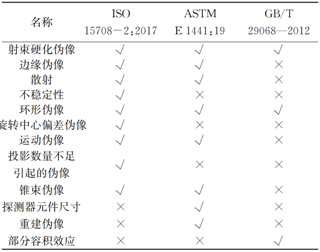
The causes of artifacts mentioned in ISO 15708-2:2017, ASTM E 1441:19, and GB/T 29068-2012 are shown below (√ indicates mentioned, × indicates not mentioned). These standards' descriptions of artifact images and their causes enable inspectors to better identify artifacts and thus effectively avoid them.
Equipment Performance Verification Methods
Performance verification requirements of each standard
| Performance parameters | ISO 15708-4 | ASTM E 1570 | GB/T 29070 |
|---|---|---|---|
| Overall performance | Compare with reference measurement results and conduct short-term checks (e.g., weekly). | Regularly measure and monitor equipment parameters and performance. | none |
| Spatial resolution | Defect detection and dimensional measurement applications | 1 time/week | ≥1 time/year; after installation, commissioning, maintenance, or replacement of parts |
| Density resolution | Defect detection applications | 1 time/week | ≥1 time/year; after installation, commissioning, maintenance, or replacement of parts |
| slice thickness | none | 1 time/week | none |
| artifact | After component quality evaluation or changes to the component | 1 time/week | |
| Component performance | none | After installation, maintenance, or component changes |
Performance verification methods for various standard equipment
| Performance parameters | ISO 15708-4 | ASTM E | GB/T |
|---|---|---|---|
| Overall performance | The reference sample is inspected, and the inspection results are compared, such as defects (porosity, cracks), thinnest point, thickest point, and thickness, to monitor the overall performance. | Verify that the spatial resolution, density resolution, and other indicators meet the usage requirements before testing (1570:19). | Verify indicators such as spatial resolution and density resolution, and validate defect detection capabilities before testing (29070-2012). |
| Spatial resolution | Disc clamping method, line clamping method | The disc card method (1695:20) | Wire-pair card method, hole-punch card method, and disc-punch card method (29069-2012). Wire-pair card method (classified into Class I, Class II, and Class III according to resolution), hole-punch card method (classified into Class I and Class II according to aperture), and disc-punch card method. Test cards can be classified by material as steel, silicon, and other metals (35391-2017). |
| Density resolution | Defect detection applications | The disc card method (1695:20) | Air gap method, density difference method, disc card method (29069-2012) Air gap method (single air, multiple air), solid density difference method, liquid density difference method, disc card method. Test cards can be classified by material as steel, aluminum, silicon and other metal test cards (35386-2017). |
| slice thickness | none | Verify using pyramids, cones, inclined planes, spiral grooves, etc. (1570:19) | none |
| artifact | Comparison with reference image | Observe the density changes of the uniform disk (1570:19) | |
| Mechanical system | Use coordinate measuring machines (CMMs) to check the displacement axis trajectory and positioning accuracy. | none | |
| Image ratio | Use a high-precision combination of spheres (such as a golf club or dumbbells) with a known spatial structure to check. | ||
| Perpendicularity of beam axis to detector | Use appropriate test samples (such as tungsten wires or fine needles, spheres, etc.) for testing. | ||
| focus | The effective focal length of X-ray tubes was measured using scanning methods, pinhole camera radiography, edge methods, and small-focal-point and micro-focal-point X-ray tubes. The dimensions obtained from CT scans at different magnifications were compared to verify that they were within the specified error range. | 2575.1-5-2010 "Focal Characteristics of Industrial X-ray Systems for Nondestructive Testing" | |
| X-ray output stability | The stability of the X-ray tube output was checked by measuring the dose rate. | none | |
| detector | Compare dynamic performance with delivery status. Regularly check for bad pixels. Verify output stability through intensity measurements over a specified period. | ||
| Reconstruction and Visualization | After reinstalling, replacing hardware, or upgrading, compare the reconstruction and visualization results with previous results. |
As can be seen from the above, the ISO standard has the most comprehensive methods and regulations for equipment performance verification. Moreover, the standard specifies the preparation methods for standard test specimens and simulated test specimens, which is sufficient to support performance verification during the daily use of equipment, and the verification cycle is the shortest. The GB standard stipulates that spatial resolution, density resolution and overall performance must be verified once a year, which is a relatively lenient requirement.
Verification of test results
| Detection purpose | ISO 15708-4 | ASTM E 1570 | GB/T |
|---|---|---|---|
| Defect detection | Verification of target feature detectability (spatial resolution, contrast resolution, reconstruction, visualization, etc.); applicability verification (verification using reference specimens combined with cross-sectional comparison); consistency verification (reconstruction, CT image scale, sine wave or CT projection sequence, system status, etc.). | Verification of whether the testing requirements are met. | Verification of standard or comparative samples (29070-2012) |
| Size measurement | Verification of dimensional measurement capabilities (spatial resolution, X-ray penetration, 3D data, etc.) | Verification of standard comparison specimens (hollow column, calibration hole array, simulated specimen) | Verification of standard or comparative samples (29070-2012) |
| Accuracy verification (using reference standard samples or reference specimens with traceable measurement capabilities for verification) | The standard sample for verifying the accuracy of dimensional measurements must be calibrated. | The standard involves dimensional measurement and calibration using a standard specimen (cubic prism), and includes requirements for standard fabrication and testing (29067-2012). | |
| Consistency verification (reconstruction, CT image scale, sine wave or CT projection sequence, system status, etc.) | -- | -- |
Conclusion
The standards of ISO, ASTM, and GB are compiled by the editors based on industry-recognized basic principles, universal experience accumulated from extensive practical operations, and product information provided by mainstream suppliers in the market. These standards have played a positive role in the application and research and development of industrial CT in China, gradually establishing a unified understanding of basic terminology and related technical requirements among equipment users and suppliers.
From the perspective of industrial CT guidelines, both GB and ASTM standards list the relationship between sample parameters and system performance and introduce the technical foundations of industrial CT, such as physical and mathematical foundations, basic algorithms, and scanning methods. The ISO standard does not mention these aspects. The ISO standard specifies precautions for samples and lists the relationship between tube voltage and penetration thickness under different materials, providing a guiding reference standard for X-ray source parameter settings. Therefore, GB and ASTM standards lean more towards fundamental principles, while the ISO standard focuses more on practical applications.
From the perspective of equipment performance evaluation, the GB standard only specifies the evaluation of overall performance, spatial resolution, and density resolution, while the ASTM standard only specifies the evaluation of overall performance, spatial resolution, density resolution, slice thickness, and artifacts. The ISO standard, in addition to the parameters mentioned above, also specifies the performance evaluation of important parameters of various components such as the focal point, detector, and mechanical system. Therefore, the ISO standard provides a more comprehensive and standardized approach to equipment performance evaluation.
From a methodological perspective, ASTM standards specifically address fan-beam CT testing, while ISO standards categorize industrial CT testing into defect detection and dimensional measurement based on testing objectives, providing detailed specifications for their procedures. GB standards, based on testing principles and experience, offer guidance on CT testing parameters such as X-ray source control. When selecting CT testing parameters, each standard should be used as needed.
 Composite Materials
 Aerospace
 Power Battery
 Automotive
 Electronics & Electrical
 Archaeology
 Geotechnical & Geology
 Biomedical
 Measurement
 Additive Manufacturing